XpressNET™ cable
XpressNET™ cables use normal telephone wire, or twin core twisted pair wire for lengths over 100 m. (300 ft.), and come equipped with three flavors of plugs:
| Plug | Employed by | |||||||||
| DIN-5 180° | Lenz | |||||||||
| Mini DIN-8 | ZTC Controls | |||||||||
| RJ-12, RJ-14 or RJ-25 | Atlas Hornby Lenz Roco |
|
||||||||
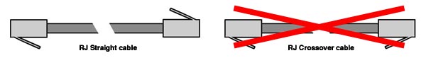
The XnTcp interface is equipped with a RJ-14 jack. If also your system uses RJ jacks, make sure to buy a straight-through connection cable with 4 (or 6) wires. In a straight-through cable the pins of one plug are connected with the same pins of the other plug (i.e. pin 1 with pin 1, pin 2 with pin 2, and so on). Be aware that most phone cords available on the market are crossover (rolled) cables (pin 1 of one plug connects with pin 6 of the other plug, pin 2 with pin 5, and so on). If you decide to build your own cable, be aware that a special crimping tool is required.
For the connection of the XnTcp interface with any command station you can use a cable with 4 or 6 wires, but if you buy/build a cable for the connection of other XpressNET™ devices, check the number of wires required on the documentation provided by their maker. Although the XpressNET™ standard uses only the 4 central pins of the RJ plug, some producers employ the remaining two pins to carry additional signals.
If your DCC system is equipped only with DIN-5 180° or Mini DIN-8 jacks, buy a RJ cable and replace one of the two plugs.
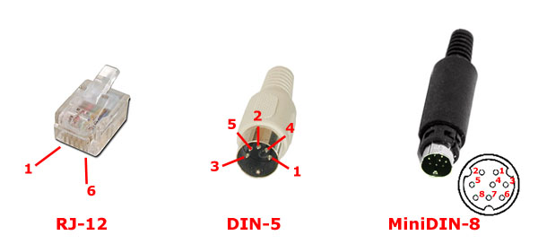
The following table reports the pins assignment of each type of plug.
| XpressNET™ signals | A | B | C* | D* | L | M | Not used |
| Meaning | RS485 A | RS485 B | Control Bus | Control Bus | +12 Volts | Ground | |
| RJ-12 pins | 4 | 3 | 1 | 6 | 5 | 2 | |
| DIN-5 pins | 4 | 5 | - | - | 1 | 3 | 2 |
| miniDIN-8 pins | 3 | 2 | 5 | 6 | 8 | 1 | 4 and 7 |
* C and D are not used by the XnTcp interface.
The above information was obtained from the XpressNET™ specifications (PDF file) and from the O Gauge in the Garden page by John Walker.
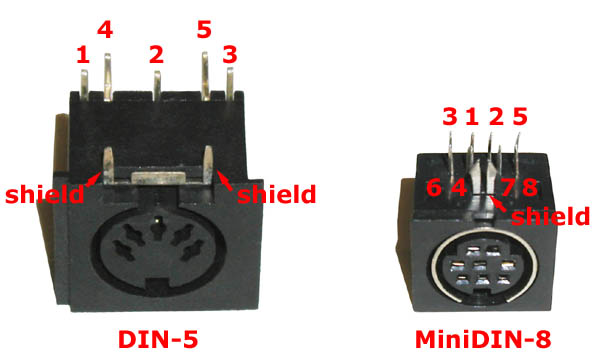
Attention: the drawing of DIN connections included in the English version of the XpressNET™ specifications is labeled "DIN plug from rear", but should likely read "DIN socket from rear".
Many thanks to Gerhard, who checked the connections on its Lenz command station and reported this problem.
Alternatively, you can mount on the prototyping board a DIN-5 180° or Mini DIN-8 jack in lieu of (or in addition to) the RJ jack.
| Jack | Supplier | Code | US$ | Remarks |
| Din-5 180° | Digikey or others | CP-2350-ND | 0.72 | Right/Angle |
| miniDIN-8 | Digikey or others | 275-1045-ND | 1.15 | Right/Angle |
The DIN-5 180° jack, owing to its size, cannot fit between the two cards and must be thus installed on the outer side of the prototyping board (i.e. opposite to the 20 pins connectors)
XpressNET™ is a trademark of Lenz Electronik, Gmbh