Components layout
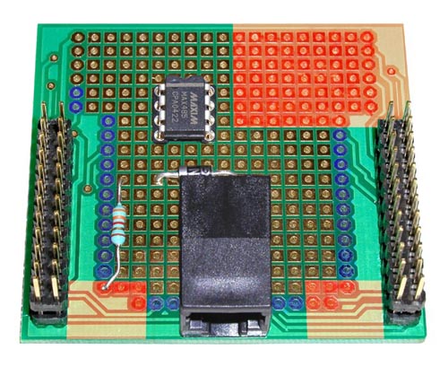
The picture shows the bottom side of the prototyping board and the suggested placement of the components.
No components must be placed on the areas shown in red, since they could interfere with the components of the SBC65EC.
Except those explicitly noted in the text, no components or wires must be soldered to the round pads (shown in blue) since these pads are connected to the PIC microprocessor.