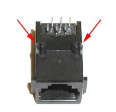
The only step of the assembly presenting some difficulties is the installation of the RJ jack. At the bottom of the RJ jack there are normally two plastic or metallic pegs for retention and two of the holes present on the prototyping board must be enlarged to host them. The grid spacing on the board is 2.54 mm. (0.1"), but the distance between the centers of the two pegs is not necessarily a multiple of this measure. The problem is easily solved by using a drill bit slightly larger than the pegs. The RJ-12 jack shown in the picture, for instance, has pegs of 3 mm. at a distance of approx. 11.5 mm (0.45") and requires two holes of 3.5 mm. spaced by 10.16 mm. (0.4"). The position and diameter of pegs can obviously vary depending on the manufacturer. |
 |
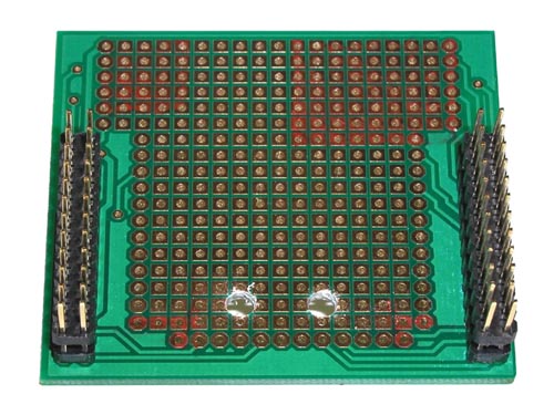 |
Before drilling, check the actual measures of your RJ jack and make sure that it can fit in the chosen location (e.g. between the prototyping board and the SBC65EC)! The jack can be alternatively mounted on the other side of the board. |
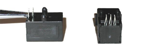
Before inserting the RJ jack in the retention holes, the tips of the pins need to be aligned. They are usually placed in two rows, offset by 1.27 mm. (0.05"), while the spacing of the holes on the board is 2.54 mm. (0.1"). A slight bend with pliers, as shown in the picture, is sufficient to obtain the alignment. |
 |
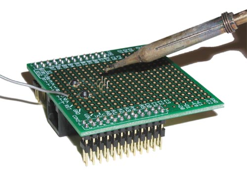
After bending the pins, place the RJ jack in its position, check on the other side of the board that the pins show through the holes, then firmly press the jack in place and solder it. Soldering of the RJ jack and of all other components must be done using a limited amount of tin, in order to avoid shortcutting neighbor pads. |
 |