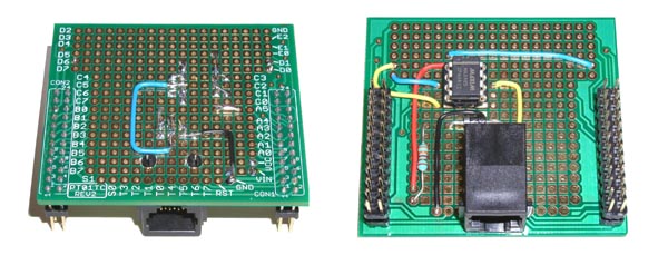
Installation of the MAX485
After completing the wiring and before inserting the IC in its socket, visually inspect the board and make sure that all wires are connected to the correct pads and pins and that no neighbor pad is shortcuted. A multimeter (either analog or digital) with the selector set to Ohm or Continuity can be of help in detecting possible shorts.
After checking the board:
- Place the MAX485 IC on its socket (paying attention to its orientation);
- Check that pins on both sides are correctly aligned with the holes of the socket;
- If pins are not aligned, use pliers to slightly bend them;
- Once the eight pins are properly aligned and their tips are in the holes, apply a slight steady pressure in the center of the chip.
|
 |
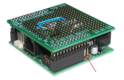 |
At this point the assembling is complete and the prototyping board can be plugged onto the SBC65EC.
Be aware that the connectors of the prototyping board have 2 rows of 12 pins, while the SBC65EC provides receptacles for two rows of 10. As shown in the picture, the last two pins of each row are therefore not connected. |